

Advanced Engine Timing Procedures: Technician’s Guide
Advanced engine timing procedures are the complete set of measurement, adjustment, and verification steps that synchronize valve events and ignition events for safe, repeatable gains in power, efficiency, and engine longevity. Get them right and you unlock performance; get them wrong and you risk valve-piston contact on interference engines, persistent knock, or a motor that runs worse than it did before you touched it.
Here is what these procedures actually cover:
- Base/initial timing — setting the ignition event relative to TDC at idle
- Mechanical and vacuum advance curves — verifying centrifugal weights and vacuum cans on distributor systems
- Cam degreeing and valve timing verification — measuring actual valve events against the cam card
- ECU timing maps — making controlled, logged changes on modern engine management systems
- Datalogging and knock management — capturing live data to find the knock limit safely
- Final verification — 720° rotation check, mark re-inspection, road test, and plug inspection
For naturally aspirated engines, typical initial timing is set at 10°–14° BTDC, with total advance often reaching 32°–36° BTDC, but always follow OEM specifications over these general ranges.
DIY vs. shop: If you have a timing light, a quality scan tool, and the OEM service manual, base timing on a distributor engine is manageable at home. Cam degreeing, ECU map editing, and anything involving an interference engine with unknown service history belong at a professional shop.
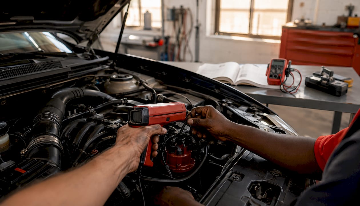
Table of Contents
- What every technician needs to know about ignition and valve timing
- How do you know if engine timing is off?
- What tools do you need, and how should you prepare?
- Step-by-step procedure for distributor ignition systems
- How do you safely adjust timing on ECU-controlled engines?
- How do you degree a cam and verify valve timing?
- Verification, testing, and fine-tuning after timing work
- What are the real risks when adjusting engine timing?
- When should you bring the vehicle to a professional shop?
- Key Takeaways
- The part most guides skip about timing work
- Tom’s B & M Auto handles timing work you should not do at home
- Authoritative references and further reading
What every technician needs to know about ignition and valve timing
Before touching a wrench, you need a shared vocabulary. Timing work involves two distinct but related systems, and confusing them is how mistakes happen.

Ignition timing is the moment the spark plug fires, expressed in degrees of crankshaft rotation before top dead center (BTDC). Fire too early and the expanding gases fight the rising piston, causing knock. Fire too late and you waste combustion energy pushing exhaust out the door.
Valve timing (cam timing) controls when the intake and exhaust valves open and close, also measured in crankshaft degrees. The camshaft turns at half crankshaft speed on a four-stroke engine, so a 4° crank change equals a 2° cam change.
TDC (top dead center) is the reference point: the piston at its highest position in the cylinder. BTDC means the crank has not yet reached TDC. Most timing specs are given in degrees BTDC.
Ignition timing on a mechanical distributor system is the sum of three components:
- Initial/base advance — the fixed advance set at idle with the vacuum line disconnected
- Mechanical (centrifugal) advance — RPM-dependent advance from flyweights inside the distributor
- Vacuum/load advance — additional advance from a vacuum can responding to manifold or ported vacuum
Modern ECUs replace all three mechanical components with timing maps driven by sensors: crankshaft position (CKP), camshaft position (CMP), manifold absolute pressure (MAP), throttle position (TPS), knock sensors, and coolant temperature. The ECU interpolates across these maps in real time, which is why ECU timing maps require a fundamentally different adjustment approach than rotating a distributor.
A note on measurement: all ignition and valve timing figures use crankshaft degrees as the unit. Piston travel is not linear with crank rotation, so always work in degrees, not millimeters of piston travel, unless the OEM spec explicitly calls for a stroke measurement (common on some diesel injection systems).
Pro Tip: Before any timing work, pull the OEM service manual for your specific engine code. Timing specs vary significantly between engine families, even within the same model year. A 2JZ-GE and a 2JZ-GTE share a block but have different base timing targets.
How do you know if engine timing is off?
Timing problems rarely announce themselves cleanly. Most symptoms overlap with ignition, fuel, or sensor faults, so the diagnostic goal is to confirm timing as the root cause before making any adjustments.
Common symptoms of incorrect timing:
- Knock or pinging under load, especially at mid-throttle
- Loss of power or flat spots during acceleration
- Hesitation on tip-in or during load transitions
- Rough idle or hunting idle
- Misfire codes (P030x series) without obvious ignition component failure
- Higher-than-normal fuel consumption
- Abnormal exhaust smoke (black for rich/retarded, occasionally blue on severe knock damage)
Stepwise diagnostic checklist:
- Connect a scan tool and pull all stored and pending DTCs. Cam/crank correlation codes (P0016, P0017, P0018, P0019) point directly to mechanical or sensor timing faults.
- Check live knock sensor data at idle and under light load. Any knock activity at idle with fresh fuel is a red flag.
- Review live spark advance. On ECU-controlled engines, compare commanded advance to actual advance. A large discrepancy suggests a sensor or actuator fault.
- Inspect spark plugs. Heavy carbon fouling suggests retarded timing or rich mixture; white/gray porcelain with erosion suggests detonation from over-advance.
- Check for vacuum leaks with a smoke machine or propane enrichment. A lean condition from a vacuum leak can mimic retarded timing symptoms.
- Perform a secondary ignition check: inspect plug wires, coil packs, and boots for carbon tracking or arcing.
The key distinction in engine timing troubleshooting is whether you are dealing with mechanical timing slip (stretched chain, worn tensioner, jumped belt tooth) or an electronic control issue (failed CKP sensor, bad knock sensor, corrupted ECU map). Mechanical slip usually produces correlation DTCs and a timing mark that no longer aligns. Electronic issues often show correct mechanical timing marks but incorrect commanded advance in live data.
Run the quick checks first: plugs, coils, vacuum integrity, and live OBD-II data. Only after ruling out those causes does it make sense to pull covers and measure.
What tools do you need, and how should you prepare?
Arriving at a timing job without the right tools wastes time and creates risk. Here is the honest breakdown.
Minimum tool list:
- Timing light (inductive, with advance dial for distributor work)
- Dial indicator with magnetic base (0.0001" resolution preferred)
- Degree wheel (at least 12" diameter for accuracy)
- Piston stop (threaded or bridge type)
- Cam and crank locking tools (OEM-specific or universal kit)
- Torque wrench (in-lb and ft-lb ranges)
- Basic hand tools, breaker bar, and harmonic balancer puller if needed
Recommended shop additions:
- Scan tool with live datalog capability (Autel, Snap-on, or equivalent)
- Wideband O2 sensor and controller (Innovate Motorsports LC-2 or AEM UEGO)
- Lab-grade tachometer or inductive RPM pickup
- Vacuum pump/gauge for bench-testing vacuum advance cans
- Laptop with logging software (HP Tuners, EFI Live, or OEM dealer software)
Preparation steps before any timing work:
- Obtain the OEM service manual for the specific engine code. Generic guides miss critical torque sequences and phasing procedures.
- Record current settings: photograph timing marks, note base timing with a light, and save a baseline datalog if the vehicle is ECU-controlled.
- Label all vacuum hoses, electrical connectors, and sensor harnesses before disconnection. A paint pen or numbered tape flags work well.
- Clear codes and capture a fresh baseline datalog before making changes.
- Disconnect the battery negative terminal only when the OEM procedure requires it. On many modern vehicles, battery disconnection resets adaptive fuel trims and causes a relearn period.
Safety checklist:
- Identify whether the engine is an interference design before removing any timing components. On interference engines, a slipped belt or chain means potential valve-piston contact the moment the engine rotates.
- Support the engine properly before removing motor mounts or front covers.
- Remove ignition sources when working near fuel lines or injectors.
- Follow OEM torque sequences for cam sprocket bolts, crank bolts, and cover fasteners. Under-torqued cam bolts are a common cause of post-service correlation DTCs.
Pro Tip: Order a timing kit (belt or chain, tensioner, idler pulleys, and water pump gasket) before you start. Replacing tensioners and idlers during a timing service costs almost nothing in added labor but eliminates the risk of a tensioner failure forcing you back into the same job in six months.
Step-by-step procedure for distributor ignition systems
Distributor systems require physical adjustment to set timing, and the procedure differs meaningfully between points-based systems and electronic pickup (HEI, TFI, DIS) distributors. The core steps apply to both.
Pre-checks before setting base timing
- Warm the engine fully to operating temperature. Timing specs are given at operating temp.
- Verify all vacuum hoses are connected and not cracked. A leaking advance hose gives a false timing reading.
- On points systems, set dwell angle first. Dwell affects timing; setting timing before dwell means you will need to re-check timing after any dwell adjustment.
- Inspect the cap, rotor, and pickup coil or points for wear, carbon tracking, or corrosion.
Base timing procedure
- Locate the OEM base timing spec and the bypass/jumper procedure for your engine. Many GM, Ford, and Toyota engines require a specific terminal to be grounded or a connector to be unplugged to disable electronic spark advance before base timing can be set. Always remove jumpers and re-enable normal modes after adjustment.
- Connect the timing light’s inductive pickup to the number-one spark plug wire. Connect power leads to the battery.
- With the engine at the specified idle RPM, aim the timing light at the timing marks on the harmonic balancer and timing cover. Identify the TDC mark and the degree scale.
- Loosen the distributor hold-down clamp just enough to allow rotation.
- Rotate the distributor housing until the timing mark aligns with the OEM-specified degree. Clockwise rotation typically retards timing; counterclockwise advances it (verify for your engine).
- Tighten the hold-down clamp to spec and recheck timing. Tightening can shift the distributor slightly.
- Reconnect the bypass connector or remove the jumper wire. Verify timing advances as RPM increases.
Mechanical advance check
- Increase engine RPM in steps (typically 1,500, 2,500, and 3,500 RPM) while watching the timing mark with the light.
- Record total advance at each RPM step. Compare to the OEM advance curve or the distributor manufacturer’s spec.
- If advance comes in too slowly or not at all, the centrifugal weights or springs are worn. Springs can be replaced or swapped for lighter/heavier sets to reshape the curve.
- If advance is excessive at low RPM, heavier springs or a limiter plate are needed.
Vacuum advance check
- Disconnect the vacuum line from the advance can and connect a hand vacuum pump.
- Apply vacuum in steps (5, 10, 15 in-Hg) and watch the timing mark. The distributor plate should rotate smoothly and hold vacuum without bleeding down.
- A can that bleeds vacuum or does not advance the full specified degrees needs replacement.
- Manifold vacuum gives advance at idle (improves fuel economy); ported vacuum gives advance only off-idle (reduces NOx). Use whichever the OEM specifies.
How do you safely adjust timing on ECU-controlled engines?
Modern engines do not have a distributor to rotate. Timing lives in the ECU’s spark advance tables, and changing it requires a different mindset: controlled, logged, incremental.
The core risk with ECU timing work is that mechanical distributor systems have no knock protection. Modern ECUs use knock sensors to dynamically pull timing when detonation occurs. Advancing timing increases power only up to the knock limit; past that point, you are damaging the engine. The ECU’s knock retard is a safety net, not a tuning strategy.
Safe ECU timing workflow
- Back up the stock tune. Before any map edit, save the original ECU calibration file to at least two locations. This is non-negotiable. An ECU reflash gone wrong without a backup can leave you with an unrunnable vehicle.
- Capture a baseline datalog. Log the following channels at a minimum: RPM, TPS, MAP or MAF, coolant temperature, spark advance (commanded and actual), knock sensor counts, short-term and long-term fuel trims, and wideband AFR. Sample at 20–50 ms intervals.
- Make one change at a time. Add 1°–2° of advance in the mid-load, mid-RPM cells first. Never edit the entire table at once.
- Test under load. Street pulls in second or third gear from 2,000–5,000 RPM give useful data, but a load dyno gives repeatable, controlled conditions. On a dyno, you can hold steady-state RPM/load points and watch knock counts in real time.
- Find the knock limit, then back off. Advance until the knock sensor shows activity, then retard 2°–3° from that point. That is your safe operating advance for that cell.
- Verify fuel trims after timing changes. Advancing timing leans the mixture slightly. If fuel trims shift significantly positive after a timing change, the fueling map may need adjustment before further timing work.
- Re-enable all stock modes and verify no DTCs before returning the vehicle to normal use.
Required datalog channels:
- Crank/cam position correlation
- RPM and TPS
- MAP or MAF
- Knock sensor counts or knock retard degrees
- Commanded and actual spark advance
- Short-term and long-term fuel trims
- Wideband AFR
- Coolant temperature
Pro Tip: Save your baseline datalog file with the date, mileage, and fuel octane in the filename before any edits. When something goes wrong three months later, that file is the only way to know what “normal” looked like. Archive it somewhere off the vehicle, not just on the laptop you bring to the track.
How do you degree a cam and verify valve timing?
Degreeing a cam is the only way to confirm that a camshaft is installed at its correct phasing. Cam cards list theoretical specs; the degree wheel tells you what the engine actually has.
Step-by-step cam degreeing procedure
- Find true TDC. Install a piston stop in the number-one spark plug hole. Rotate the crank clockwise until the piston contacts the stop; record the degree wheel reading. Rotate counterclockwise until the piston contacts the stop again; record that reading. True TDC is the midpoint between the two readings. Zero the degree wheel to that point.
- Mount the dial indicator. Position it on the number-one intake valve retainer (or lifter/follower), perpendicular to valve travel. Zero the indicator with the valve fully closed.
- Find the .050" opening point. Rotate the crank slowly until the dial indicator reads .050" of lift. Record the degree wheel reading. This is intake open at .050".
- Find the .050" closing point. Continue rotating until the valve returns to .050" lift on the closing side. Record that reading. This is intake close at .050".
- Calculate intake centerline. Add intake open and intake close (both in degrees ATDC/ABDC as appropriate), then divide by two. Compare to the cam card spec.
- Repeat for the exhaust lobe. Record exhaust open and exhaust close at .050".
- Calculate lobe separation angle (LSA). LSA = (intake centerline + exhaust centerline) / 2. A tighter LSA increases overlap and moves the powerband higher; a wider LSA broadens the curve and reduces overlap.
What the numbers tell you
| Measurement | What it reveals |
|---|---|
| Intake centerline vs. cam card | Whether cam is advanced, retarded, or on spec |
| Lobe separation angle | Overlap characteristics and powerband bias |
| Intake open/close at — | Actual duration; compare to advertised duration |
| Exhaust open/close at — | Scavenging characteristics |
Advancing the cam (smaller intake centerline number) increases low-end torque and moves the powerband down. Retarding it shifts power higher in the RPM range. A 3-keyway crank sprocket allows ±4° of crankshaft adjustment (±2° at the cam) without offset keys or custom sprockets.
VVT and VANOS systems
Variable valve timing systems add electrical indexing to the mechanical procedure. After setting mechanical phasing, verify solenoid actuation with a multimeter: check resistance against spec and confirm the solenoid moves the phaser through its range in service mode. Improper electrical indexing causes camshaft position correlation DTCs even when the mechanical timing marks are perfectly aligned. Always torque cam phaser bolts to spec in the correct sequence, and rotate the engine 720° before final assembly to confirm no binding.
Pro Tip: On VVT engines, clear all DTCs after reassembly and run the engine through a full warm-up cycle before checking for returning codes. Some correlation DTCs are stored from the disassembly process and will not return if the phasing is correct.
Verification, testing, and fine-tuning after timing work
No timing job is complete until the engine has been verified under real conditions. Reassembly is the beginning of the process, not the end.
Post-reassembly verification checklist:
- Manually rotate the engine two full revolutions (720°) by hand before the first start. This confirms no valve-piston contact and that all timing marks return to their expected positions. On interference engines, skipping this step is how engines get destroyed on the first crank.
- Re-check all timing marks visually before installing covers.
- Verify all bolt torques on cam sprockets, crank bolt, and cover fasteners.
- Reconnect all bypasses, jumpers, and vacuum lines.
- Clear all DTCs and monitor for immediate returns on first start.
Datalogging template for post-timing verification:
- Cold start: log coolant temp, idle RPM, spark advance, and fuel trims from first crank through full warm-up.
- Light-load cruise: log AFR stability, advance vs. commanded advance, and knock counts at 30–50 mph in light throttle.
- Moderate acceleration: second-gear pull from 2,000–4,500 RPM. Watch for knock events and advance pull-back.
- Full-load sweep: only on a dyno or a safe, controlled environment. Log peak advance, knock activity, and AFR across the full RPM range.
Fine-tuning approach:
Look for AFR stability within the target window (typically 13.5:1–14.7:1 at cruise, richer under full load). Any knock retard activity during the moderate acceleration pull means the advance table needs to come back in that cell. On a dyno, torque response to small timing changes is visible immediately; on the street, plug color after a hard pull is a useful secondary indicator.
Road-test protocol:
- Avoid full-load testing until the engine has reached full operating temperature.
- Run at least three pulls before drawing conclusions from datalog data. Coolant temp, intake air temp, and fuel octane all affect knock threshold.
- Pull the plugs after the first 100 miles and inspect for signs of detonation: speckled insulator, rounded electrode, or aluminum deposits on the ground strap.
What are the real risks when adjusting engine timing?
Timing work has a short list of mistakes that cause catastrophic damage. Most of them are avoidable with discipline.
High-risk mistakes:
- Guessing timing without a timing light or degree wheel
- Locking only the cam without verifying crank sprocket position (friction-fit sprockets can slip)
- Skipping the 720° rotation check on interference engines
- Forgetting to remove bypass jumpers before first start, which prevents electronic advance from functioning
- Making large timing map changes without logging baseline data first
Common failure modes after improper timing:
- Valve-piston contact on interference engines: bent valves, damaged pistons, and sometimes a destroyed head. This is the worst-case outcome, and it happens fast.
- Persistent cam/crank correlation DTCs (P0016–P0019) after reassembly, usually from incorrect phasing or a VVT solenoid not re-indexed properly.
- Premature wear on timing chain guides and tensioners when tension is set incorrectly after reassembly.
Parts to replace proactively during timing service:
Tensioners, idler pulleys, and the water pump are standard replacement items during any timing belt or chain service. The added parts cost is modest; the labor to revisit the job if a tensioner fails six months later is not. On belt-driven engines, always replace the belt, tensioner, idler, and water pump as a set.
Pro Tip: Apply a small amount of thread locker (medium-strength, such as Loctite 243) to cam sprocket bolts only when the OEM procedure calls for it. On some engines, thread locker is specified; on others, it is explicitly prohibited. Check the manual.
When should you bring the vehicle to a professional shop?
Some timing jobs are genuinely DIY-friendly. Others are not, and the cost of getting it wrong is an engine rebuild.
Clear indicators to use a professional:
- Interference engine with unknown service history or a suspected jumped belt/chain
- ECU remapping needs beyond simple base timing adjustments
- VVT/VANOS indexing issues with persistent correlation DTCs
- Persistent knock that is not explained by fuel octane or obvious sensor faults
- Lack of OEM-specific special service tools (SSTs) for cam locking or phaser indexing
- No access to a scan tool with live datalog capability
What a professional shop does that is hard to replicate at home:
- OEM-specific phasing with SSTs that prevent cam or crank sprocket slip during assembly
- ECU reflashes with dealer or professional-grade software and verified calibration files
- Dyno tuning with steady-state load testing and real-time knock mapping
- Warranty-backed replacement of all wear items (tensioners, idlers, seals, water pump)
- Pre- and post-service datalogs that document the condition before and after the job
Time and cost context: A timing belt job on a typical four-cylinder typically runs 3–5 labor hours at a shop; a timing chain job on a V6 or V8 can run 6–10 hours or more depending on access. ECU tuning sessions vary widely by platform and scope. Shop work carries a warranty; DIY does not.
What to request from your shop:
- Pre-service datalog or baseline timing check documentation
- List of all replaced parts with part numbers
- Torque records for critical fasteners
- Post-service datalog confirming timing marks and advance behavior
- Written warranty terms for parts and labor
For readers in the Lynnwood area, timing belt service at a shop with ASE-certified technicians and a documented warranty is the lower-risk path on any interference engine.
Key Takeaways
Correct engine timing requires precise measurement, incremental adjustment, and verified confirmation under load before any job is considered complete.
| Point | Details |
|---|---|
| Diagnose before adjusting | Use OBD-II live data and DTCs to confirm timing is the root cause before opening the engine. |
| Interference engines demand caution | Always rotate 720° by hand after reassembly; valve-piston contact destroys engines on the first crank. |
| ECU timing needs logged evidence | Datalog baseline channels before and after every map change; advance incrementally to the knock limit, then back off 2°–3°. |
| Replace wear items during service | Tensioners, idlers, and the water pump should be replaced during any timing belt or chain job to avoid repeat labor. |
| Tom’s B & M Auto | ASE-certified timing belt, chain, and ECU diagnostic services in Lynnwood, WA, backed by a 24-month/24,000-mile warranty. |
The part most guides skip about timing work
Timing work gets treated as a single adjustment when it is really a diagnostic and measurement process with a physical adjustment at the end. The adjustment is the easy part. The hard part is confirming you have the right answer before you make it.
The most common mistake I see described in post-mortem threads and shop discussions is not over-advancing timing. It is skipping the diagnostic step entirely: someone hears knock, rotates the distributor, and the knock goes away temporarily because they retarded the engine into a safe zone. But the knock was caused by a lean condition from a vacuum leak, not by over-advance. Now the engine is retarded, makes less power, and the vacuum leak is still there.
The second most common mistake is treating ECU timing work as equivalent to distributor rotation. It is not. A distributor change affects all operating conditions simultaneously. An ECU timing map change can be targeted to specific load and RPM cells, which means you can advance timing exactly where the engine needs it and leave conservative timing everywhere else. That precision is the real advantage of modern engine management, and it is wasted if you treat it like a single-knob adjustment.
For complex cases, particularly VVT systems with correlation DTCs or any interference engine that has not had documented timing service, the right call is a shop with OEM tooling and datalog capability. The engine repair services at Tom’s B & M Auto include cam/crank alignment verification, ECU diagnostics, and post-service datalogs that document the result. That paper trail matters when the engine is under warranty or when you need to prove the work was done correctly.
Tom’s B & M Auto handles timing work you should not do at home
For interference engines, VVT systems, or any timing job that requires ECU diagnostics and datalog verification, Tom’s B & M Auto in Lynnwood, WA is the practical alternative to guessing at home with incomplete tools. The shop has served Toyota, Honda, Subaru, domestic, European, and hybrid owners since 1985, with ASE-certified technicians and a 24-month/24,000-mile warranty on all work.
Services relevant to timing include timing belt and chain replacement, cam/crank alignment with OEM-specific tooling, check-engine-light diagnostics, and full engine repair for post-timing issues. Same-day appointments are often available. If your check-engine light is on and you suspect a timing or cam correlation fault, start with a free check-engine-light review to confirm the root cause before any parts are ordered. Larger timing jobs may qualify for financing options to spread the cost. Book online or call the Lynnwood shop directly.
Authoritative references and further reading
These sources support the procedures and specifications in this guide. Always cross-reference with the OEM service manual for your specific engine code before making any adjustments.
- OEM service manuals (Helm, Toyota TIS, Honda Service Express, Mitchell1, AllData): the only authoritative source for model-specific torque values, timing specs, and SST part numbers. No generic guide replaces them.
- Ignition timing overview (UTI): clear explanation of why timing accuracy affects power, economy, and engine survival, useful for building foundational understanding.
- Ignition timing (Wikipedia): covers the components of total advance and the transition from mechanical to ECU-controlled systems.
- Engine timing (Wikipedia): explains the relationship between valve events and ignition events and the role of the timing system in the combustion cycle.
- NASA Glenn Research Center timing system overview: a clear mechanical explanation of how cam and ignition timing systems interact, useful for visual learners building a mental model.
- NTN-SNR engine timing service bulletin: professional guidance on replacing ancillary components (tensioners, idlers, water pump) during timing service.
- Cloyes 3-keyway installation guide (DocsLib): practical reference for cam phasing adjustments using offset sprockets on GM and Ford applications.
- HP Tuners and EFI Live documentation: platform-specific guides for ECU datalog channel setup and timing map editing; available through each platform’s support portal.
- Tom’s B & M Auto timing belt services: local professional timing service with warranty, for readers who prefer shop work over DIY.
This article is general technical information, not a substitute for the OEM service manual or professional advice for your specific vehicle. Confirm all specs, torque values, and procedures with the primary source for your engine before beginning any timing work.
Recommended
- Fix Engine Misfires Step by Step: A Car Owner’s Guide – Tom’s B & M Auto Blog
- Common Honda Repair Needs: Your 2026 Owner’s Guide – Tom’s B & M Auto Blog
- Why Your Car Hesitates During Acceleration: 2026 Guide – Tom’s B & M Auto Blog
- ASE Certification Benefits for Mechanics: Career Guide – Tom’s B & M Auto Blog
Leave a Reply